
Foreword Tech Tips:
We would like to take care of the basic little things that hopefully will be of help to newcomers to our beautiful hobby. The more experienced who always know exactly how it should be done should be aware that usually there is more than one right way. We do not want to fundamentally question procedures here, we want to give tips and tricks from our point of view. The tips are, of course, left to everyone who considers them sensible and would like to implement them if necessary. As I said, we would like to offer added value for those who are interested, and try to provide solutions that either respond to frequently asked questions or appear to us to be worth knowing in the daily model making. However, it should not be a pure FAQ page. We want to try to offer something more than just "answering questions" on a regular basis.
Have fun with our FTTs (Fumotec Tech Tips)
With the introduction of lipo (lithium polymer) batteries and brushless drives, there were unimagined performance and unimagined possibilities in our beautiful hobby.
But the new technologies did not only bring advantages. The initially complicated handling still deters many modelers. Therefore, it is even more important to know your "tools of the trade" and that is why we have decided to give you useful and helpful explanations about model building and especially about our models under the heading "Tech Tips".
Explanation of the information on the battery:
For example, a battery 3S1P with 5000 mAh and 35C discharge current and max. 3C charge current:
3S1P means that the battery is made of 3 cells soldered in series (positive terminal to negative terminal) (that's what the S stands for). The P stands for parallel and means that in addition to the serial soldering, the battery has parallel (positive pole to positive pole, negative pole to negative pole) soldering to increase the capacity and the load capacity (the discharge and charge current). In general one uses almost exclusively only serially soldered battery packs, therefore 1P is written here.
5000 mAh means that the capacity of the battery is 5000 mAh or 5 Amp-hours. This number describes the "amount of electricity" that the battery has. In the same model, you can dig longer with a 5000 mAh battery than with a 4000 mAh battery.
11.1 V means that the battery has a nominal voltage of 11.1 V. Each lithium polymer cell has a nominal voltage of 3.7 V. This voltage is multiplied by 3 (since we have 3 cells in the battery). This gives us the nominal voltage of 11.1 V. The cell has the nominal voltage approximately in the delivery state, it is only fully charged to about 20% here. Practical operation should already be finished when the nominal voltage is reached. A fully charged Lithium Polymer cell has a voltage of 4.2 V. Multiplied by 3, this results in a total voltage of 12.6 V in the fully charged battery. This is also the cut-off voltage for the charger.
35C means that the battery may be permanently loaded with a maximum of 35C (35 x 5Ah results in 175 amps).
3C means that the battery may be charged with a maximum of 3C (3 x 5Ah results in 15 amps) charging current. (lower currents protect the battery).
Even in functional model construction, brushless controllers are now part of the basic equipment of a model. Being as a pump drive or, as in our models, as a travel drive.
But where "brushed" systems mostly work "plug and play", "brushless" systems need a little more attention beforehand. But you will be rewarded in retrospect with longer battery life, more performance, and less wear and tear.
TIMING VALUE AND NUMBER OF POLES
Timing is nothing more than a time setting that is proportional to the position of the rotor in degrees.
Timing in electric motors is roughly equivalent to the function of early ignition in internal combustion engines.
The correct timing setting is very important to optimize an engine.
Responsible for the timing setting is the controller, which passes the voltage distribution to the motor.
If a controller switches voltage to a motor, the voltage is immediately available at full level,
the current, however, does not flow immediately at full strength, but is set with a time delay.
This of course costs motor power, since the magnetic fields in the coils are built up or reduced too late.
Without an adjustment, the magnetic fields do not optimally match the magnets in terms of timing.
An indication of incorrectly set timing are the "screeching/squealing noises" of the motor.
These are not only annoying but can also damage the motor.
So the voltage must arrive earlier.
Of course, this all happens within fractions of a second and varies from motor to motor.
The timing depends on the pole number, inductance and the operating voltage.
Fewer poles usually have lower timing values.
Simplified this means :
Lower timing values = lower current = lower power = lower motor speed = less heat in the motor = longer battery life.
Higher timing values = higher current = more power = higher motor speed = more heat in the motor = shorter battery life.
Guide values for the timing selection (observe manufacturer's specifications):
0 - 12 for 2 6 pole motors (internal rotor).
13 -- 22 for 6 12 pole motors (external rotor).
22 - 30 for 12 16 pole motors (large external rotors).
Summarized again :
The whole point of timing is that
temporal adjustment of the commutation time compared to the magnetic field. This is necessary because the motor winding is "charged" with inductance, which means that the current does not set until later, ie. delayed a. Therefore, the current flow must be started earlier.
The exact timing value must be matched to the engine.
The higher the timing, the more current the motor draws. The appropriate setting must be selected depending on the number of poles of the brushless motor.
Without screw locking, a long-term operation without failures is unthinkable with functional models (incidentally also with almost all other models).
Therefore all drive elements must be secured. In addition to the generally different strengths of the screw locks available on the market, it makes a considerable difference in how the screw lock is used.
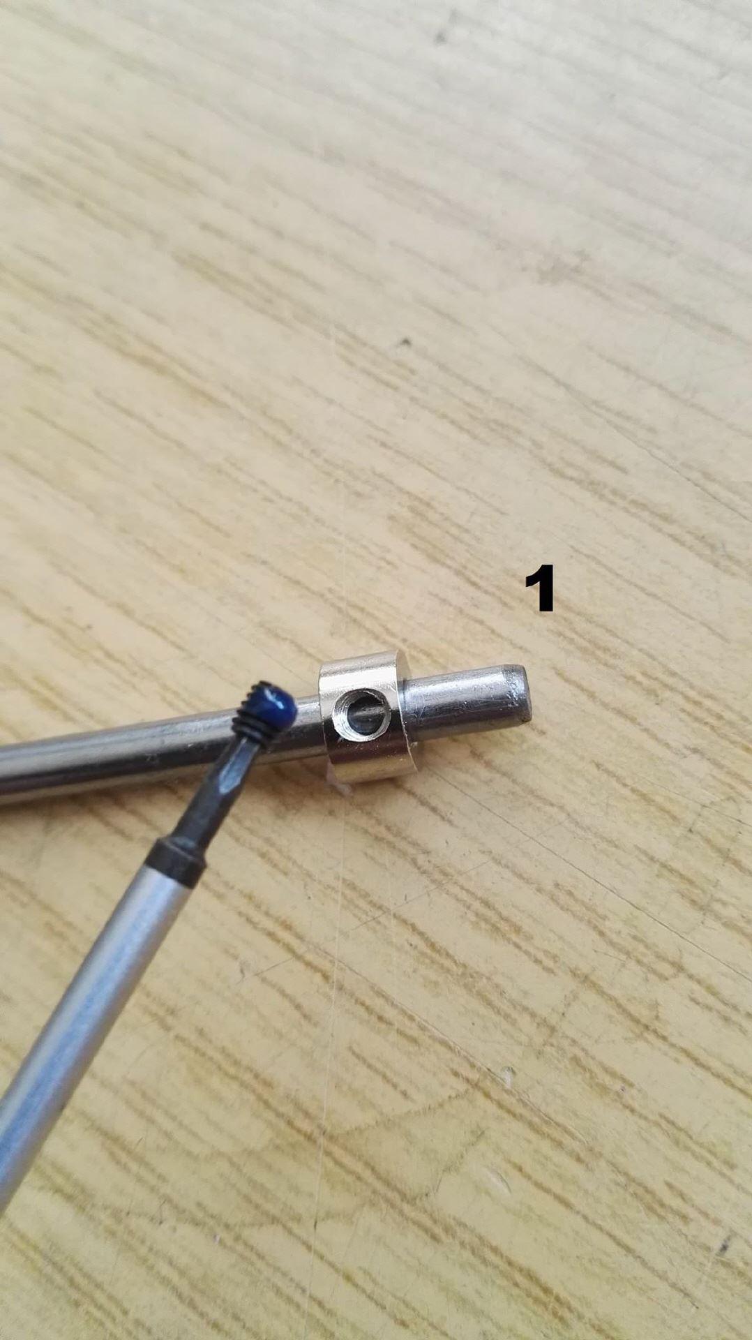
Threadlocker in the thread or on the screw / made?
For "normal" screw connections where a secure connection is important, but both the screw and the part to be mounted on a shaft (gear wheel, hub, whatever) would like to open and dismantle again without any problems, the screw locking device is recommended to wear the thread of the screw. When screwing in, part of the thread locker strips off to the outside and can be wiped off. The screw is secured in the thread but can be loosened again. The part mounted on a shaft can easily be removed again.
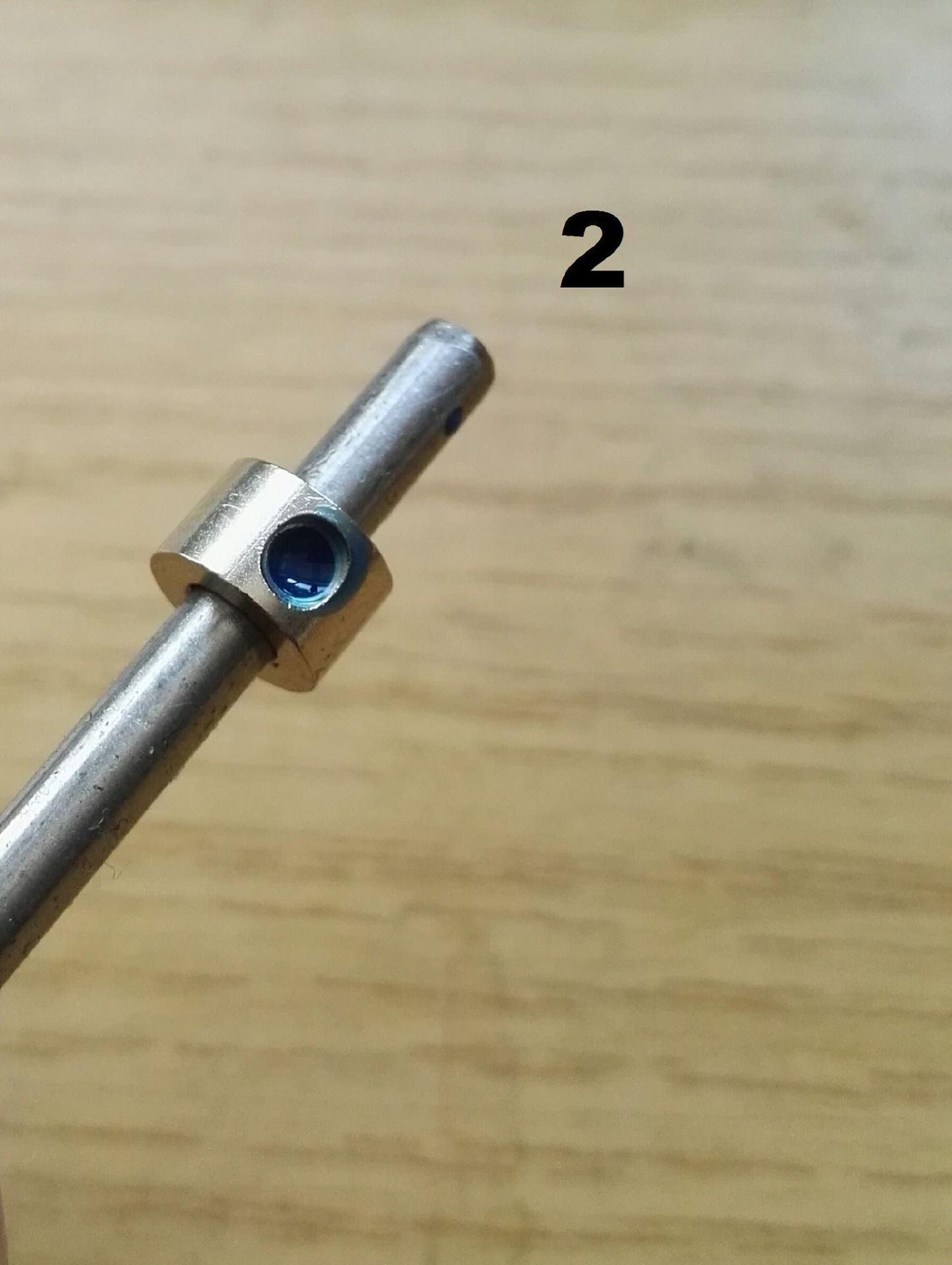
When it really matters......
When it comes to driving components, especially where high torques must be transmitted (here, for example, especially chain drives and swing gears in the excavator), or other places where you want to be on the safe side, you should go a different way. Here, it is better to apply the thread locker in the thread. When the screw is screwed in, the excess thread locker is pushed forward. The screw now acts like a piston in the cylinder and pushes the thread locker in front of it until the thread locker is pressed between the gear and the shaft (or whatever is being mounted). Since the thread locker is a kind of "metal glue", the screw itself is of course secured, but in addition, the gear is glued to the shaft. A connection that even with the use of a medium-strength thread locker is usually only solved by strong heating.
1. the suction line (Fumotec Shop-ID:15-13) between pump and tank
should always be as short and thick as possible.
2. If possible, do not use elbow fittings with a small opening.
If elbow fittings are required, then with 90 elbows for
full cross-section.
Use e.g. push-in connector 90 with 6mm (Fumotec Shop-ID:
15-59) and 8mm (Fumotec Shop-ID: 15-58) or our M5 brass
Contra-angle handpieces (Fumotec Shop-ID: 15-136)
3. The oil level in the tank should always be above the pump, but at least at the same height so that the pump does not have to suck in the oil.
4. The lines between the pump and the valve block should be thicker than the individual lines from the valve block to the cylinders. (E.g. Ø6mm
Fumotec Shop-ID: 15-12)
5. Ideally the return lines (Fumotec Shop-ID: 15-14) from the valve block to the tank should be thicker than those from the pump to the
Valve block in order to avoid backpressure. (If necessary, double return to run)
6. The return lines should always end below the oil level in the tank, otherwise, the oil will foam up.
7. Ideally the return and suction lines between the pump and the tank should be transparent lines, so that you can see any air bubbles, etc.. (Fumotec Shop ID:15-13 & 15-14)
8. The filters (Fumotec Shop-ID: 15-68) are always built into the return line in the hydraulic systems like in the original
Machines.